This website uses cookies to ensure you get the best experience on our website. Read policy
MUTOH ValueJet VJ-1617H MAINTENANCE Service and Parts Manual
In stock
SKU
MU-1617H-SM
$9.90
- Email with download link immediately
- Files without viruses
- PDF format manual
- Allow high-definition printing
MUTOH ValueJet VJ-1617H
MAINTENANCE Service and Parts Manual

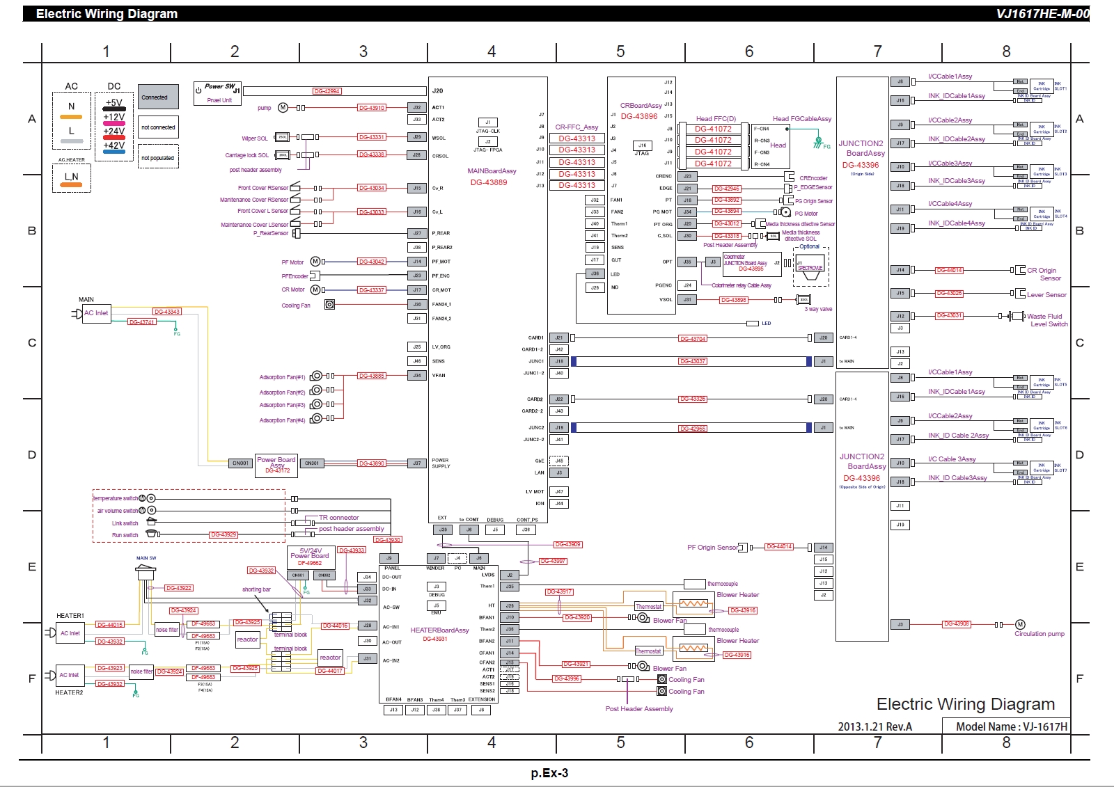
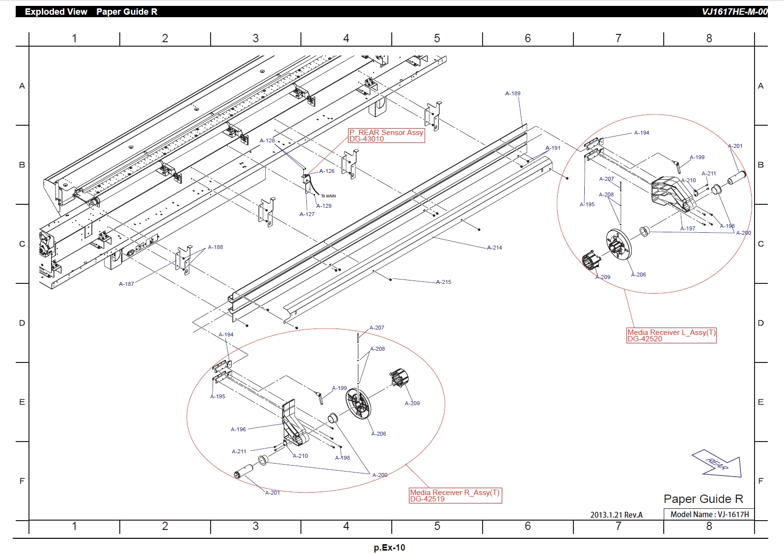

1 Safety Instructions
1.1 Introduction . . . . . . . . . . . . . . . . . . . . . . . . . . . . . . . . . . . . 1-2
1.2 Types and Meanings of Warnings . . . . . . . . . . . . . . . . . . 1-2
1.3 Warning Labels . . . . . . . . . . . . . . . . . . . . . . . . . . . . . . . . . 1-3
1.3.1 Handling the Warning Labels. . . . . . . . . . . . . . . . . . . . 1-3
1.3.2 Location and Type of Warning Labels . . . . . . . . . . . . . 1-3
2 Troubleshooting
2.1 Introduction . . . . . . . . . . . . . . . . . . . . . . . . . . . . . . . . . . . . 2-2
2.2 Troubleshooting with Error Messages. . . . . . . . . . . . . . . 2-3
2.2.1 Operation Status . . . . . . . . . . . . . . . . . . . . . . . . . . . . . 2-3
2.2.2 Errors with Message . . . . . . . . . . . . . . . . . . . . . . . . . . 2-6
2.2.3 Errors Requiring Reboot . . . . . . . . . . . . . . . . . . . . . . 2-11
2.2.4 Error Messages During File Transmission. . . . . . . . . 2-24
2.3 Troubleshooting Without Error Messages . . . . . . . . . . 2-27
2.3.1 Initial Operation Problems . . . . . . . . . . . . . . . . . . . . . 2-27
2.3.2 Media Feed Problems . . . . . . . . . . . . . . . . . . . . . . . . 2-33
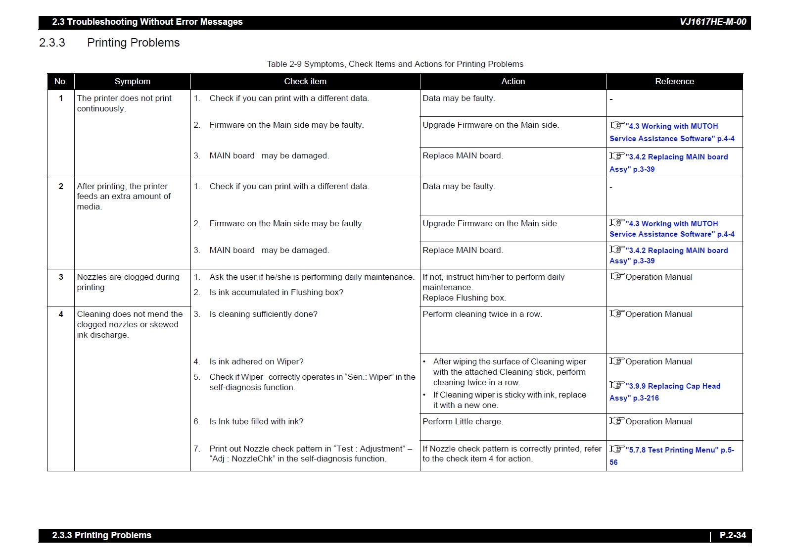
2.3.3 Printing Problems . . . . . . . . . . . . . . . . . . . . . . . . . . . 2-34
2.3.4 Noise Problems . . . . . . . . . . . . . . . . . . . . . . . . . . . . . 2-46
2.3.5 Online Function Problems . . . . . . . . . . . . . . . . . . . . . 2-49
2.3.6 Other Problems . . . . . . . . . . . . . . . . . . . . . . . . . . . . . 2-50
2.3.7 Problems in Using MUTOH Service Assistance . . . . 2-52
3 Part Replacement
3.1 Introduction . . . . . . . . . . . . . . . . . . . . . . . . . . . . . . . . . . . . 3-6
3.2 Removing Covers. . . . . . . . . . . . . . . . . . . . . . . . . . . . . . . . 3-7
3.2.1 Removing Maintenance Cover . . . . . . . . . . . . . . . . . . 3-8
3.2.2 Removing Maintenance Cover U . . . . . . . . . . . . . . . . . 3-9
3.2.3 Removing Side Maintenance Cover . . . . . . . . . . . . . 3-10
3.2.4 Removing IH Cover . . . . . . . . . . . . . . . . . . . . . . . . . . 3-11
3.2.5 Removing Side Top Cover. . . . . . . . . . . . . . . . . . . . . 3-12
3.2.6 Removing Sub Tank Cover R . . . . . . . . . . . . . . . . . . 3-13
3.2.7 Removing Sub Tank Cover L. . . . . . . . . . . . . . . . . . . 3-14
3.2.8 Removing Front Cover. . . . . . . . . . . . . . . . . . . . . . . . 3-15
3.2.9 Removing Heater Unit Cover . . . . . . . . . . . . . . . . . . . 3-16
3.2.10 Removing Nozzle Base . . . . . . . . . . . . . . . . . . . . . . . 3-18
3.2.11 Removing Top Cover (Heater Unit) . . . . . . . . . . . . . . 3-20
3.2.12 Removing Paper Guide F . . . . . . . . . . . . . . . . . . . . . 3-22
3.2.13 Removing Rear Lever Cover . . . . . . . . . . . . . . . . . . . 3-23
3.2.14 Removing Paper Guide R (Upper). . . . . . . . . . . . . . . 3-24
3.2.15 Removing Paper guide R (lower) . . . . . . . . . . . . . . . 3-25
3.2.16 Removing Panel Cover . . . . . . . . . . . . . . . . . . . . . . . 3-26
3.3 Replacing Cover Peripherals. . . . . . . . . . . . . . . . . . . . . . 3-28
3.3.1 Replacing Panel Unit . . . . . . . . . . . . . . . . . . . . . . . . . 3-28
3.3.2 Replacing Panel FFC. . . . . . . . . . . . . . . . . . . . . . . . . 3-29
3.3.3 Replacing Cover switch Assy. . . . . . . . . . . . . . . . . . . 3-31
3.3.4 Replacing Cover R Cable Assy. . . . . . . . . . . . . . . . . 3-36
3.3.5 Replacing Cover L Cable Assy . . . . . . . . . . . . . . . . . 3-37
3.4 Replacing Board Base . . . . . . . . . . . . . . . . . . . . . . . . . . . 3-38
3.4.1 Opening Board box . . . . . . . . . . . . . . . . . . . . . . . . . . 3-38
3.4.2 Replacing MAIN board Assy . . . . . . . . . . . . . . . . . . . 3-39
3.4.3 Replacing AC Inlet . . . . . . . . . . . . . . . . . . . . . . . . . . . 3-41
3.4.4 Replacing FG Cable. . . . . . . . . . . . . . . . . . . . . . . . . . 3-42
3.4.5 Replacing MAIN_DC Cable Assy . . . . . . . . . . . . . . . 3-43
3.4.6 Replacing JUNCTION board . . . . . . . . . . . . . . . . . . . 3-44
3.4.7 Replacing JUNC_ID Cable . . . . . . . . . . . . . . . . . . . . 3-46
3.4.8 Replacing JUNC_FFC . . . . . . . . . . . . . . . . . . . . . . . . 3-47
3.4.9 Replacing Power Board . . . . . . . . . . . . . . . . . . . . . . . 3-49
3.4.10 Replacing Cooling FAN . . . . . . . . . . . . . . . . . . . . . . . 3-50
3.5 Replacing Blower Heater section . . . . . . . . . . . . . . . . . . 3-52
3.5.1 Replacing HEATER Board. . . . . . . . . . . . . . . . . . . . . 3-52
3.5.2 Replacing 5V/24V Power Board . . . . . . . . . . . . . . . . 3-54
3.5.3 Replacing DC Cable . . . . . . . . . . . . . . . . . . . . . . . . . 3-55
3.5.4 Replacing AC_IN1 Cable, AC_IN2 Cable . . . . . . . . . 3-56
3.5.5 Replacing Terminal Block-P/S Cable Assy. . . . . . . . 3-57
3.5.6 Replacing Fuse-Terminal Block Cable Assy. . . . . . . 3-58
3.5.7 Replacing Fuse . . . . . . . . . . . . . . . . . . . . . . . . . . . . . 3-59
3.5.8 Replacing Rocker Switch. . . . . . . . . . . . . . . . . . . . . . 3-60
3.5.9 Replacing AC Inlet . . . . . . . . . . . . . . . . . . . . . . . . . . . 3-61
3.5.10 Replacing AC Cable 1Assy, AC Cable 2Assy . . . . . . 3-62
3.5.11 Replacing Line Filter Cable 1Assy. . . . . . . . . . . . . . . 3-63
3.5.12 Replacing AC_SW Control Cable Assy . . . . . . . . . . . 3-64
3.5.13 Replacing Line Filter Cable 2Assy. . . . . . . . . . . . . . . 3-65
3.5.14 Replacing Line Filter . . . . . . . . . . . . . . . . . . . . . . . . . 3-66
3.5.15 Replacing Reactor . . . . . . . . . . . . . . . . . . . . . . . . . . . 3-67
3.5.16 Replacing Cooling FAN, Cooling FAN Relay cable . . 3-68
3.5.17 Removing Heater Panel Cover . . . . . . . . . . . . . . . . . 3-70
3.5.18 Replacing Push-Button Switch Assy . . . . . . . . . . . . . 3-71
3.5.19 Replacing RUN_SW Relay Cable . . . . . . . . . . . . . . . 3-72
3.5.20 Replacing LINK_SW Cable . . . . . . . . . . . . . . . . . . . . 3-73
3.5.21 Replacing Temperature Control Switch . . . . . . . . . . . 3-74
3.5.22 Replace Air Volume Control Switch. . . . . . . . . . . . . . 3-75
3.5.23 Replacing Panel Cable . . . . . . . . . . . . . . . . . . . . . . . 3-76
3.5.24 Replacing Blower FAN. . . . . . . . . . . . . . . . . . . . . . . . 3-77
3.5.25 Replacing Blower FAN Relay Cable . . . . . . . . . . . . . 3-78
3.5.26 Replacing Heater Cable. . . . . . . . . . . . . . . . . . . . . . . 3-79
3.5.27 Replacing Thermostat, Thermostat Relay Cable. . . . 3-81
3.5.28 Replacing Blower Heater Assy . . . . . . . . . . . . . . . . . 3-83
3.5.29 Replacing Temperature Measuring Sensor . . . . . . . . 3-85
3.6 Replacing X Rail Section . . . . . . . . . . . . . . . . . . . . . . . . . 3-87
3.6.1 Replacing X Speed Reduction Belt . . . . . . . . . . . . . . 3-87
3.6.2 Replacing PF Encoder . . . . . . . . . . . . . . . . . . . . . . . . 3-91
3.6.3 Replacing PF Encoder Scale, PF Speed Reduction Pulley
3-93
3.6.4 Replacing PF Motor Assy . . . . . . . . . . . . . . . . . . . . . 3-97
3.6.5 Replacing PF Motor Relay Assy . . . . . . . . . . . . . . . 3-100
3.6.6 Replacing PF Origin Sensor, PF Origin Sensor Cable . 3-
101
3.6.7 Replacing PF Origin Sensor Cable . . . . . . . . . . . . . 3-103
3.6.8 Replacing Adsorption FAN Cable . . . . . . . . . . . . . . 3-104
3.6.9 Replacing Vacuum Fan Assy. . . . . . . . . . . . . . . . . . 3-105
3.6.10 Replacing Timing Belt Assy . . . . . . . . . . . . . . . . . . . 3-106
3.6.11 Replacing P_Rear Sensor . . . . . . . . . . . . . . . . . . . . 3-108
3.6.12 Replacing Lever sensor, Lever sensor cable. . . . . . 3-110
3.6.13 Replacing Platen Non-Reflecting Tape . . . . . . . . . . 3-112
3.6.14 Replacing Media Holder. . . . . . . . . . . . . . . . . . . . . . 3-113
3.6.15 Replacing Pressure roller. . . . . . . . . . . . . . . . . . . . . 3-114
3.6.16 Replacing Pressure Roller Retainer Assy . . . . . . . . 3-115
3.7 Replacing Y Rail section . . . . . . . . . . . . . . . . . . . . . . . . 3-116
3.7.1 Replacing Steel belt . . . . . . . . . . . . . . . . . . . . . . . . . 3-116
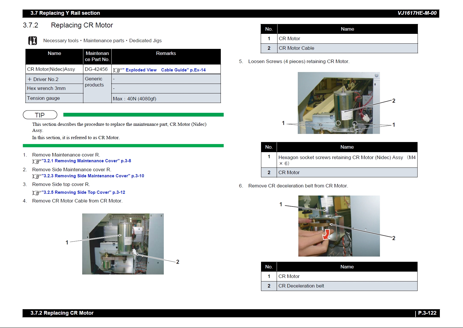
3.7.2 Replacing CR Motor. . . . . . . . . . . . . . . . . . . . . . . . . 3-122
3.7.3 Replacing CR Deceleration Belt . . . . . . . . . . . . . . . 3-124
3.7.4 Replacing CR deceleration pulley . . . . . . . . . . . . . . 3-128
3.7.5 Replacing CR Motor Cable Assy . . . . . . . . . . . . . . . 3-131
3.7.6 Replacing CR Return Pulley . . . . . . . . . . . . . . . . . . 3-132
3.7.7 Replacing T Fence. . . . . . . . . . . . . . . . . . . . . . . . . . 3-134
3.7.8 Replacing CR Origin Sensor Cable . . . . . . . . . . . . . 3-136
3.7.9 Replacing CR Origin Sensor . . . . . . . . . . . . . . . . . . 3-137
3.7.10 Replacing Steel Bare . . . . . . . . . . . . . . . . . . . . . . . . 3-138
3.7.11 Replacing CR_FFC . . . . . . . . . . . . . . . . . . . . . . . . . 3-140
3.7.12 Replacing Ink Tube . . . . . . . . . . . . . . . . . . . . . . . . . 3-144
3.8 Replacing Carriage Section . . . . . . . . . . . . . . . . . . . . . 3-157
3.8.1 Releasing Carriage Lock . . . . . . . . . . . . . . . . . . . . . 3-157
3.8.2 Replacing CR Lock Solenoid Cable. . . . . . . . . . . . . 3-158
3.8.3 Replacing Carriage Lock Solenoid . . . . . . . . . . . . . 3-159
3.8.4 Removing Carriage Cover . . . . . . . . . . . . . . . . . . . . 3-160
3.8.5 Removing Head Cover . . . . . . . . . . . . . . . . . . . . . . 3-161
3.8.6 Removing CR board Cover . . . . . . . . . . . . . . . . . . . 3-162
3.8.7 Replacing CR board . . . . . . . . . . . . . . . . . . . . . . . . 3-163
3.8.8 Replacing CR Encoder Assy . . . . . . . . . . . . . . . . . . 3-165
3.8.9 Replacing Three-way Solenoid Valve . . . . . . . . . . . 3-167
3.8.10 Replacing Three-way solenoid valve relay cable. . . 3-169
3.8.11 Replacing LED Pointer . . . . . . . . . . . . . . . . . . . . . . 3-170
3.8.12 Replacing Colorimeter Junction Board Assy
(Removing Bracket) 3-172
3.8.13 Replacing Cutter SOL Cable Assy. . . . . . . . . . . . . . 3-174
3.8.14 Removing Media Thickness Detection Unit . . . . . . . 3-175
3.8.15 Replacing Cutter Solenoid Assy . . . . . . . . . . . . . . . 3-176
3.8.16 Replacing Cutter Solenoid Spring Assy. . . . . . . . . . 3-178
3.8.17 Replacing PG Origin Sensor Cable . . . . . . . . . . . . . 3-179
3.8.18 Replacing P_EDGE Sensor. . . . . . . . . . . . . . . . . . . 3-180
3.8.19 PG Variable Motor Relay Assy . . . . . . . . . . . . . . . . 3-181
3.8.20 Replacing PG Motor . . . . . . . . . . . . . . . . . . . . . . . . 3-183
3.8.21 Replacing Valve Head Assy . . . . . . . . . . . . . . . . . . 3-185
3.8.22 Replacing Connector Valve Head . . . . . . . . . . . . . . 3-189
3.8.23 Replacing Print Head. . . . . . . . . . . . . . . . . . . . . . . . 3-191
3.8.24 Replacing Head FFC . . . . . . . . . . . . . . . . . . . . . . . . 3-195
3.8.25 Replacing Cursor Roller Arm Assy . . . . . . . . . . . . . 3-197
3.8.26 Replacing Carriage Assy . . . . . . . . . . . . . . . . . . . . . 3-199
3.9 Replacing Maintenance Section . . . . . . . . . . . . . . . . . . 3-205
3.9.1 Removing Maintenance Inner Cover . . . . . . . . . . . . 3-205
3.9.2 Replacing Flushing Box . . . . . . . . . . . . . . . . . . . . . . 3-206
3.9.3 Replacing Waste Fluid Tray Assy . . . . . . . . . . . . . . 3-207
3.9.4 Replacing Waste Fluid Pump. . . . . . . . . . . . . . . . . . 3-208
3.9.5 Replacing PUMP Rear relay Assy . . . . . . . . . . . . . . 3-209
3.9.6 Replacing Wiper. . . . . . . . . . . . . . . . . . . . . . . . . . . . 3-211
3.9.7 Replacing Wiper Solenoid Cable . . . . . . . . . . . . . . . 3-212
3.9.8 Replacing Wiper Solenoid . . . . . . . . . . . . . . . . . . . . 3-214
3.9.9 Replacing Cap Head Assy . . . . . . . . . . . . . . . . . . . . 3-216
3.9.10 Replacing Maintenance Assy. . . . . . . . . . . . . . . . . . 3-218
3.9.11 Replacing Waste Fluid Sensor Cable Assy . . . . . . . 3-220
3.10 Replacing IH section . . . . . . . . . . . . . . . . . . . . . . . . . . . 3-221
3.10.1 Removing Slot Cover . . . . . . . . . . . . . . . . . . . . . . . . 3-221
3.10.2 Replacing Cartridge Holder Assy. . . . . . . . . . . . . . . 3-222
3.10.3 Replacing Ink ID Board Assy . . . . . . . . . . . . . . . . . . 3-224
3.10.4 Replacing Circulation Pump. . . . . . . . . . . . . . . . . . . 3-226
3.10.5 Replacing Circulation Pump Relay Cable . . . . . . . . 3-228
3.11 Replacing Leg Section. . . . . . . . . . . . . . . . . . . . . . . . . . 3-229
3.11.1 Replacing Waste Fluid Bottle and Waste Fluid Level
Switch 3-229
3.11.2 Replacing Waste Fluid Sensor Cable Assy . . . . . . . 3-231
3.12 Replacing Roll media receiving section. . . . . . . . . . . . 3-233
3.12.1 Replacing Media Receiver . . . . . . . . . . . . . . . . . . . . 3-233
3.13 Replacing Take-up Unit Section (Option). . . . . . . . . . . 3-234
3.13.1 Removing Tension Arm . . . . . . . . . . . . . . . . . . . . . . 3-234
3.13.2 Removing Take-up Unit . . . . . . . . . . . . . . . . . . . . . . 3-235
3.13.3 Removing Take-up Cover . . . . . . . . . . . . . . . . . . . . 3-236
3.13.4 Replacing Scroller . . . . . . . . . . . . . . . . . . . . . . . . . . 3-237
3.13.5 Replacing Take-up Control Board Assy. . . . . . . . . . 3-240
3.13.6 Replacing Take-up ON Sensor and Take-up OFF Sensor
3.13.7 Replacing Peripheral Devices of Take-up Motor Assy . 3-
249
3.14 Replacing Large size Winding Unit Section (Option) . 3-252
3.14.1 Removing FW circuit board box. . . . . . . . . . . . . . . . 3-252
3.14.2 Replacing FW Control Board Assy . . . . . . . . . . . . . 3-256
3.14.3 Replacing FW DC Switch Cable Assy, 5V/24V Power
Board 3-257
3.14.4 Replacing FW AC Switch Cable Assy、FG Cable Assy、
AC Inlet 3-259
3.14.5 Removing Feed and roll upper surface cover . . . . . 3-262
3.14.6 Replacing Winder Flange Assy and Roller . . . . . . . 3-263
3.14.7 Replacing Flange (Return) Assy and Roller . . . . . . 3-265
3.14.8 Replacing Feeding Center Gear Assy . . . . . . . . . . . 3-266
3.14.9 Replacing Winder Motor Gear Assy . . . . . . . . . . . . 3-267
3.14.10Replacing ROLL Motor Assy . . . . . . . . . . . . . . . . . . 3-268
3.14.11Replacing Feeding Sensor Plate Assy and Feeding Sensor
(Feed unit side) 3-269
3.14.12Replacing Feeding Sensor Plate Assy and Rolling Sensor
(ROLL Unit side) 3-272
3.14.13Replacing F_Sensor cable Assy . . . . . . . . . . . . . . . 3-275
3.14.14Replacing F_Motor cable Assy . . . . . . . . . . . . . . . . 3-276
3.14.15Replacing W_Sensor Cable Assy . . . . . . . . . . . . . . 3-277
3.14.16Replacing W_Motor cable Assy. . . . . . . . . . . . . . . . 3-278
3.14.17Replacing F_SW Cable Assy . . . . . . . . . . . . . . . . . 3-279
3.14.18Replacing W_SW Cable Assy . . . . . . . . . . . . . . . . . 3-281
3.14.19Replacing FSW Board Assy、WSW Board Assy . . 3-283
4 Adjustment
4.1 Introduction . . . . . . . . . . . . . . . . . . . . . . . . . . . . . . . . . . . . 4-2
4.2 Adjustment Item . . . . . . . . . . . . . . . . . . . . . . . . . . . . . . . . . 4-2
4.3 Working with MUTOH Service Assistance Software. . . . 4-4
4.3.1 Parameter Backup . . . . . . . . . . . . . . . . . . . . . . . . . . . . 4-4
4.3.2 Jigs and Tools . . . . . . . . . . . . . . . . . . . . . . . . . . . . . . . 4-4
4.3.3 Required Environment . . . . . . . . . . . . . . . . . . . . . . . . . 4-4
4.3.4 Updating Date and Time . . . . . . . . . . . . . . . . . . . . . . 4-17
4.3.5 Editing Media Type . . . . . . . . . . . . . . . . . . . . . . . . . . 4-18
4.3.6 Acquiring and Saving Error Log . . . . . . . . . . . . . . . . . 4-20
4.3.7 Updating main firmware . . . . . . . . . . . . . . . . . . . . . . . 4-22
4.3.8 Installing Blower Heater F/W . . . . . . . . . . . . . . . . . . . 4-23
4.3.9 Receiving Backup Parameters. . . . . . . . . . . . . . . . . . 4-25
4.3.10 Sending Backup Parameter . . . . . . . . . . . . . . . . . . . . 4-26
4.3.11 Board Replacement Wizard . . . . . . . . . . . . . . . . . . . . 4-27
4.3.12 Diagnostic Mode . . . . . . . . . . . . . . . . . . . . . . . . . . . . 4-33
4.3.13 Acquiring Printer Identification Data. . . . . . . . . . . . . . 4-40
4.3.14 Sending Authorization code . . . . . . . . . . . . . . . . . . . . 4-41
4.3.15 Referring Set Up Information . . . . . . . . . . . . . . . . . . . 4-42
4.3.16 Referring Adjustment Parameter . . . . . . . . . . . . . . . . 4-44
4.3.17 Initializing activation . . . . . . . . . . . . . . . . . . . . . . . . . . 4-46
4.3.18 Version Information . . . . . . . . . . . . . . . . . . . . . . . . . . 4-47
4.3.19 Terminating Application . . . . . . . . . . . . . . . . . . . . . . . 4-48
4.4 Steel Belt Tension Adjustment . . . . . . . . . . . . . . . . . . . . 4-49
4.4.1 Adjustment Procedure . . . . . . . . . . . . . . . . . . . . . . . . 4-49
4.5 CR Speed Reduction Belt Tension Adjustment. . . . . . . 4-51
4.5.1 Adjustment Procedure . . . . . . . . . . . . . . . . . . . . . . . . 4-51
4.6 X Speed Reduction Belt Tension Adjustment . . . . . . . . 4-53
4.6.1 Adjustment Procedure . . . . . . . . . . . . . . . . . . . . . . . . 4-53
4.7 Head Accuracy Adjustment. . . . . . . . . . . . . . . . . . . . . . . 4-54
4.7.1 Head Alignment (Horizontal Slant). . . . . . . . . . . . . . . 4-54
4.7.2 Head Alignment (Vertical Slant). . . . . . . . . . . . . . . . . 4-57
4.8 Head Height Adjustment . . . . . . . . . . . . . . . . . . . . . . . . . 4-60
4.8.1 Adjusting 21.5mm . . . . . . . . . . . . . . . . . . . . . . . . . . . 4-60
4.8.2 Adjusting 1.5mm . . . . . . . . . . . . . . . . . . . . . . . . . . . . 4-62
4.9 Rear/ Edge Sensor Adjustment . . . . . . . . . . . . . . . . . . . 4-63
5 Self Diagnosis Function
5.1 Introduction . . . . . . . . . . . . . . . . . . . . . . . . . . . . . . . . . . . . 5-3
5.2 Preparation . . . . . . . . . . . . . . . . . . . . . . . . . . . . . . . . . . . . . 5-3
5.2.1 Preparations on Machine. . . . . . . . . . . . . . . . . . . . . . . 5-3
5.2.2 Starting Up. . . . . . . . . . . . . . . . . . . . . . . . . . . . . . . . . . 5-4
5.3 Operations in Self-Diagnosis Mode . . . . . . . . . . . . . . . . . 5-5
5.3.1 Operating Self-Diagnosis Mode. . . . . . . . . . . . . . . . . . 5-5
5.3.2 Diagnosis Items in Self-Diagnosis Menu . . . . . . . . . . . 5-6
5.4 Head height adjustment . . . . . . . . . . . . . . . . . . . . . . . . . . 5-7
5.5 Test Menu . . . . . . . . . . . . . . . . . . . . . . . . . . . . . . . . . . . . . . 5-9
5.5.1 Memory Size Menu . . . . . . . . . . . . . . . . . . . . . . . . . . 5-11
5.5.2 Version Menu. . . . . . . . . . . . . . . . . . . . . . . . . . . . . . . 5-12
5.5.3 Operation Panel Menu. . . . . . . . . . . . . . . . . . . . . . . . 5-13
5.5.4 Sensor Menu . . . . . . . . . . . . . . . . . . . . . . . . . . . . . . . 5-14
5.5.5 Check Menu. . . . . . . . . . . . . . . . . . . . . . . . . . . . . . . . 5-16
5.5.6 Encoder Menu . . . . . . . . . . . . . . . . . . . . . . . . . . . . . . 5-18
5.5.7 Fan Menu. . . . . . . . . . . . . . . . . . . . . . . . . . . . . . . . . . 5-19
5.5.8 Record Menu . . . . . . . . . . . . . . . . . . . . . . . . . . . . . . . 5-20
5.5.9 Head Waveform Menu. . . . . . . . . . . . . . . . . . . . . . . . 5-28
5.5.10 Media thick Menu. . . . . . . . . . . . . . . . . . . . . . . . . . . . 5-29
5.5.11 SPECTROVUE Menu . . . . . . . . . . . . . . . . . . . . . . . . 5-30
5.5.12 Time Check Menu . . . . . . . . . . . . . . . . . . . . . . . . . . . 5-31
5.5.13 Heater check Menu . . . . . . . . . . . . . . . . . . . . . . . . . . 5-32
5.6 Ink Charging Menu . . . . . . . . . . . . . . . . . . . . . . . . . . . . . . 5-33
5.7 Adjustment Menu . . . . . . . . . . . . . . . . . . . . . . . . . . . . . . . 5-34
5.7.1 Rear/ Edge Sensor Adjustment . . . . . . . . . . . . . . . . . 5-35
5.7.2 Head Nozzle Check Menu . . . . . . . . . . . . . . . . . . . . . 5-37
5.7.3 Skew Check Menu . . . . . . . . . . . . . . . . . . . . . . . . . . . 5-40
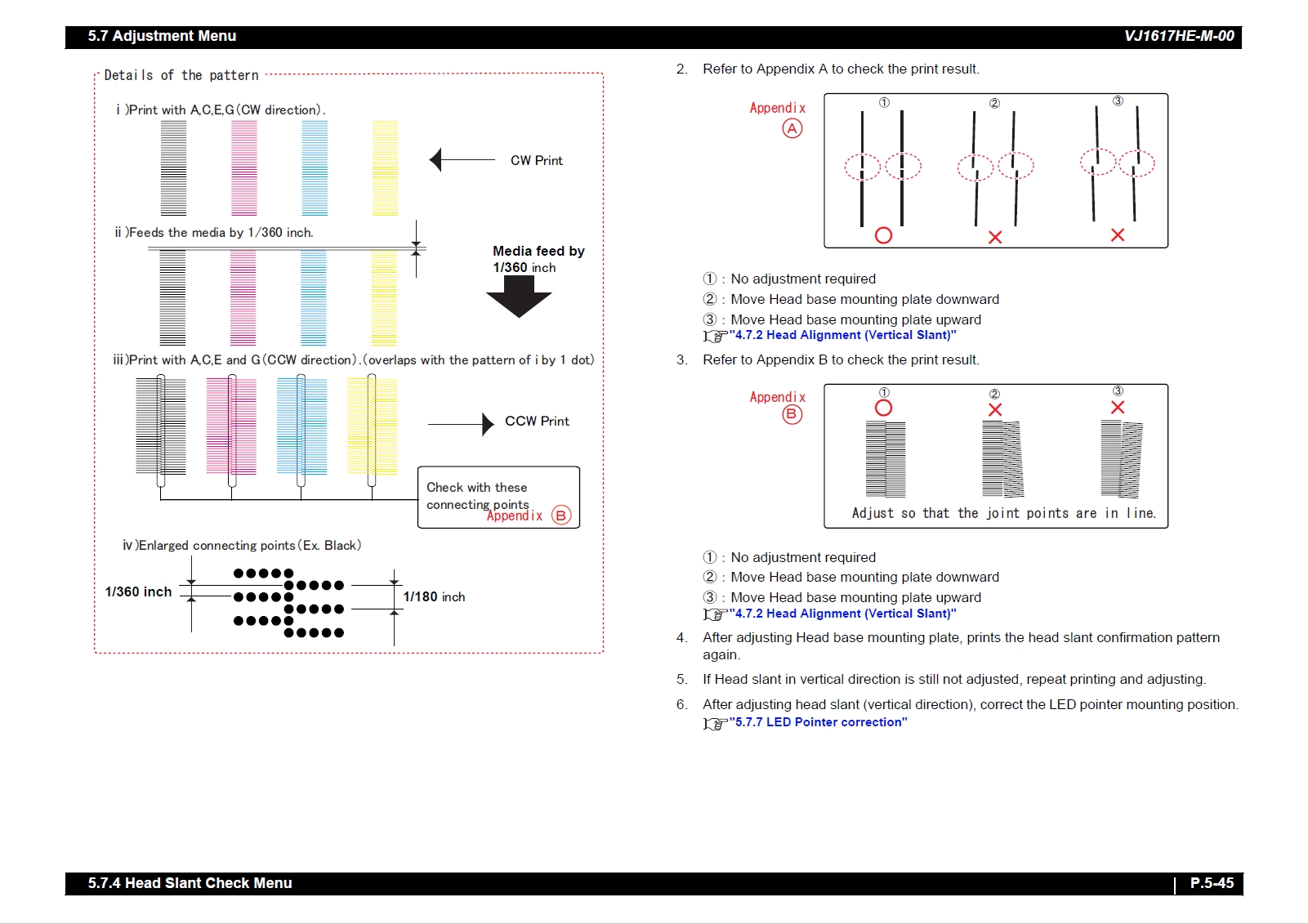
5.7.4 Head Slant Check Menu . . . . . . . . . . . . . . . . . . . . . . 5-41
5.7.5 Uni-D/ Bi-D Adjustment Menu . . . . . . . . . . . . . . . . . . 5-46
5.7.6 Margin adjustment Menu . . . . . . . . . . . . . . . . . . . . . . 5-54
5.7.7 LED Pointer correction. . . . . . . . . . . . . . . . . . . . . . . . 5-55
5.7.8 Test Printing Menu. . . . . . . . . . . . . . . . . . . . . . . . . . . 5-56
5.7.9 Longstore Menu . . . . . . . . . . . . . . . . . . . . . . . . . . . . . 5-57
5.7.10 Longstore2 Menu. . . . . . . . . . . . . . . . . . . . . . . . . . . . 5-58
5.7.11 Software Counter Initialization Menu . . . . . . . . . . . . . 5-59
5.7.12 Feed Pitch Check Menu. . . . . . . . . . . . . . . . . . . . . . . 5-60
5.7.13 Solid Print Menu. . . . . . . . . . . . . . . . . . . . . . . . . . . . . 5-61
5.8 Cleaning Menu. . . . . . . . . . . . . . . . . . . . . . . . . . . . . . . . . 5-62
5.9 Sample printing Menu . . . . . . . . . . . . . . . . . . . . . . . . . . . 5-63
5.10 Parameter Menu . . . . . . . . . . . . . . . . . . . . . . . . . . . . . . . . 5-64
5.10.1 Parameter Initialization Menu . . . . . . . . . . . . . . . . . . 5-65
5.10.2 Parameter Update Menu . . . . . . . . . . . . . . . . . . . . . . 5-66
5.11 Servo Setting Menu . . . . . . . . . . . . . . . . . . . . . . . . . . . . . 5-75
5.12 Endurance Running Menu. . . . . . . . . . . . . . . . . . . . . . . . 5-76
5.12.1 CR Motor Endurance Menu . . . . . . . . . . . . . . . . . . . . 5-77
5.12.2 PF Motor Endurance Menu . . . . . . . . . . . . . . . . . . . . 5-78
5.12.3 Pump Endurance Menu . . . . . . . . . . . . . . . . . . . . . . . 5-79
5.12.4 C Pump endurance Menu . . . . . . . . . . . . . . . . . . . . . 5-80
5.12.5 Head Lock Menu . . . . . . . . . . . . . . . . . . . . . . . . . . . . 5-81
5.12.6 Wiper Endurance menu . . . . . . . . . . . . . . . . . . . . . . . 5-82
5.12.7 PG Solenoid Endurance Menu . . . . . . . . . . . . . . . . . 5-83
5.12.8 Head U/D Endurance Menu. . . . . . . . . . . . . . . . . . . . 5-84
5.12.9 Print Head Endurance (Nozzle Print) Menu. . . . . . . . 5-85
5.12.10General Endurance Menu . . . . . . . . . . . . . . . . . . . . . 5-86
5.12.11Endurance Running Check Menu . . . . . . . . . . . . . . . 5-87
5.13 Paper Feed Menu . . . . . . . . . . . . . . . . . . . . . . . . . . . . . . . 5-88
5.14 Paper Initial Menu . . . . . . . . . . . . . . . . . . . . . . . . . . . . . . 5-89
6 Maintenance Mode 2
6.1 Introduction . . . . . . . . . . . . . . . . . . . . . . . . . . . . . . . . . . . . 6-2
6.2 Operations in Maintenance Mode 2 . . . . . . . . . . . . . . . . . 6-2
6.2.1 Starting Up the Maintenance Mode 2 . . . . . . . . . . . . . 6-2
6.2.2 Operating Maintenance Mode 2 . . . . . . . . . . . . . . . . . 6-3
6.3 Maintenance Mode 2 Menu . . . . . . . . . . . . . . . . . . . . . . . . 6-4
6.3.1 Counter Indication Menu . . . . . . . . . . . . . . . . . . . . . . . 6-5
6.3.2 Counter Initialization Menu . . . . . . . . . . . . . . . . . . . . 6-15
6.3.3 Cleaning Menu. . . . . . . . . . . . . . . . . . . . . . . . . . . . . . 6-16
6.3.4 Counter Print Menu . . . . . . . . . . . . . . . . . . . . . . . . . . 6-17
6.3.5 Paper Feed Menu . . . . . . . . . . . . . . . . . . . . . . . . . . . 6-18
7 Maintenance
7.1 Introduction . . . . . . . . . . . . . . . . . . . . . . . . . . . . . . . . . . . . 7-2
7.2 Periodical Services . . . . . . . . . . . . . . . . . . . . . . . . . . . . . . 7-3
7.2.1 Periodic Replacement Parts . . . . . . . . . . . . . . . . . . . . 7-3
7.2.2 Parts Which Require Inspection/Replacement . . . . . . 7-3
7.3 Part Life Information . . . . . . . . . . . . . . . . . . . . . . . . . . . . . 7-4
7.4 Jigs and Tools . . . . . . . . . . . . . . . . . . . . . . . . . . . . . . . . . . 7-5
7.4.1 Required Tools. . . . . . . . . . . . . . . . . . . . . . . . . . . . . . . 7-5
7.5 Lubrication/Bonding . . . . . . . . . . . . . . . . . . . . . . . . . . . . . 7-7
7.6 Transportation of Product . . . . . . . . . . . . . . . . . . . . . . . . . 7-8
8 Product Overview
8.1 Introduction. . . . . . . . . . . . . . . . . . . . . . . . . . . . . . . . . . . . . 8-2
8.2 Part Names and Functions . . . . . . . . . . . . . . . . . . . . . . . . 8-2
8.2.1 Front Section . . . . . . . . . . . . . . . . . . . . . . . . . . . . . . . . 8-2
8.2.2 Rear Section . . . . . . . . . . . . . . . . . . . . . . . . . . . . . . . . 8-3
8.2.3 Operation panel . . . . . . . . . . . . . . . . . . . . . . . . . . . . . . 8-4
8.2.4 Blower heater operation panel . . . . . . . . . . . . . . . . . . . 8-6
8.3 Printer Status . . . . . . . . . . . . . . . . . . . . . . . . . . . . . . . . . . . 8-7
8.3.1 Operating Status Type . . . . . . . . . . . . . . . . . . . . . . . . . 8-7
8.3.2 Switching Operating Status . . . . . . . . . . . . . . . . . . . . . 8-8
9 Specifications
9.1 Introduction. . . . . . . . . . . . . . . . . . . . . . . . . . . . . . . . . . . . . 9-2
9.2 Product Specifications. . . . . . . . . . . . . . . . . . . . . . . . . . . . 9-2
9.2.1 Main Unit Specifications. . . . . . . . . . . . . . . . . . . . . . . . 9-2
9.3 Interface specification . . . . . . . . . . . . . . . . . . . . . . . . . . . . 9-4
9.3.1 Network interface specification . . . . . . . . . . . . . . . . . . 9-4
9.4 Options/Supplies List. . . . . . . . . . . . . . . . . . . . . . . . . . . . . 9-5
9.4.1 Supplies . . . . . . . . . . . . . . . . . . . . . . . . . . . . . . . . . . . . 9-5
9.5 Coosing Place for the Printer . . . . . . . . . . . . . . . . . . . . . . 9-6
10 Appendix
10.1 Introduction . . . . . . . . . . . . . . . . . . . . . . . . . . . . . . . . . . . 10-2
10.2 Maintenance Part List . . . . . . . . . . . . . . . . . . . . . . . . . . . 10-2

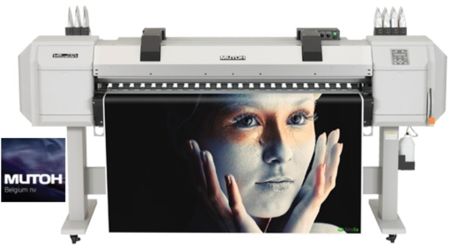

| Manual Name | MUTOH ValueJet VJ-1617H MAINTENANCE Manual |
|---|---|
| Format | |
| PDF Archive | 53.5M |
| Pages | 600 |
| Version | 1.00 |
| Brand | MUTOH |
| Parts Code | VJ1617HE-M-01 |
| Reference | 2013.3 |
| Type | SERVICE or PARTS MANUAL |
| Compatible Model | . |

