This website uses cookies to ensure you get the best experience on our website. Read more
EPSON L11160 L15150 L15160 L15180 / ET-16150 ET-16600 ET-16650 ET-16680 ST-C8000 C8090 Service Manual
In stock
SKU
EP-L15150-SM
$9.90
- Email with download link immediately
- Files without viruses
- PDF format service manual
- Allow high-definition printing
| Manual Name | EPSON L11160 L15150 L15160 L15180 / ET-16150 ET-16600 ET-16650 ET-16680 ST-C8000 C8090 Service Manual |
|---|---|
| Format | |
| PDF Archive | 68.4M |
| Pages | 250 |
| Version | F |
| Brand | EPSON |
| Type | SERVICE or PARTS MANUAL |
| Compatible Model | EPSON L11160 EPSON L15150 L15160 L15180 EPSON ECOTANK ET-16100 Series ET-16150 Epson ET-16600 Series Epson ET-16650 ET-16680 ST-C8000 ST-C8090 |
EPSON L11160 L15150 L15160 L15180
ET-16150 ET-16600 ET-16650 ET-16680
ST-C8000 ST-C8090
Service Manual

Contents
Chapter 1 Operating Principles
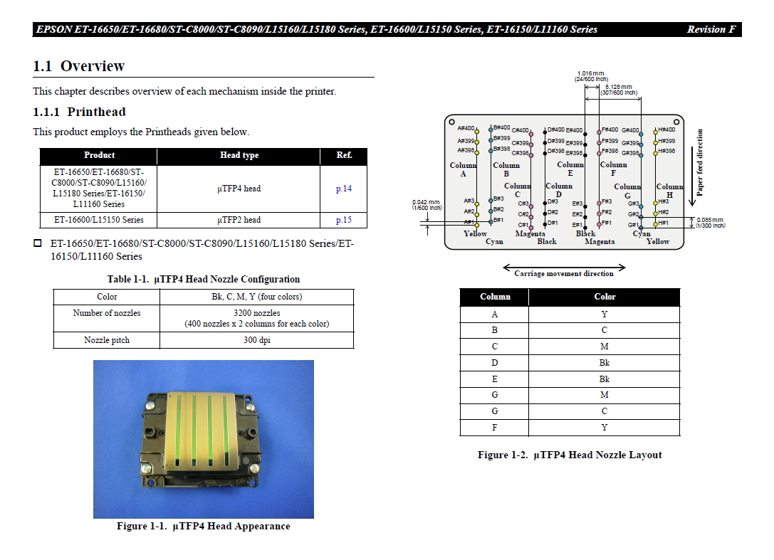
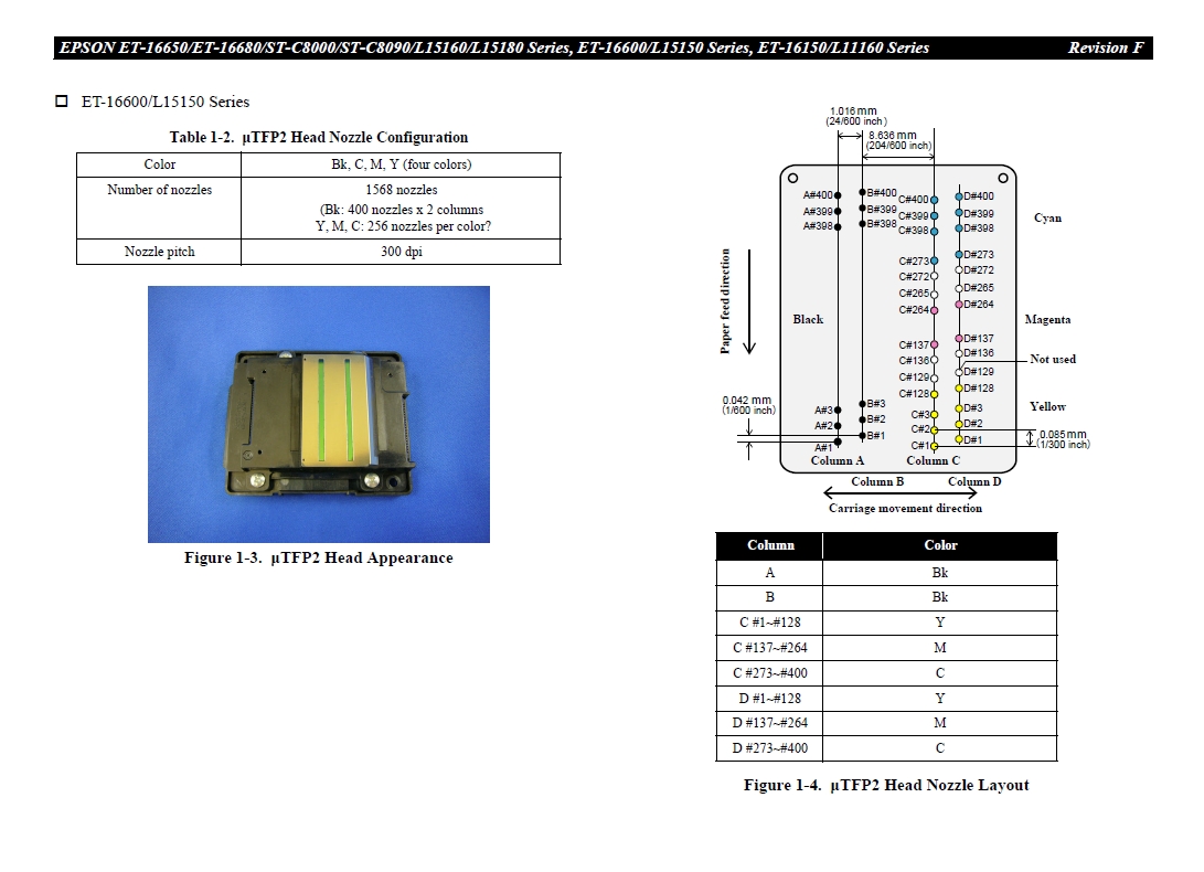
1.1 Overview .............................................................................................................. 14
1.1.1 Printhead ...................................................................................................... 14
1.1.1.1 Head Angular Mecha Adjustment (ET-16650/ET-16680/ST-C8000/STC8090/
L15160/L15180 Series/ET-16150/L11160 Series only).......................16
1.1.2 Carriage Mechanism / APG Mechanism ..................................................... 17
1.1.3 Paper Loading/Feed Mechanism ................................................................. 18
1.1.4 Ink Supply Mechanism................................................................................ 19
1.1.5 Ink System Mechanism................................................................................ 20
1.1.6 Scanner Mechanism (Except for ET-16150/L11160 Series)....................... 21
1.1.7 ADF Mechanism (Except for ET-16150/L11160 Series)............................ 22
1.1.8 List of Motor and Sensor ............................................................................. 24
1.2 APG Mechanism Operating Principles ................................................................ 26
1.2.1 Overview...................................................................................................... 26
1.2.2 Operating Principles .................................................................................... 27
1.2.2.1 Driving Path .........................................................................................27
1.2.2.2 PG Type ...............................................................................................28
1.3 Paper Loading/Feed Mechanism Operating Principles ........................................ 29
1.3.1 Overview...................................................................................................... 29
1.3.1.1 Paper Feeding Path ..............................................................................30
1.3.2 Operating Principles .................................................................................... 33
1.3.2.1 Driving Path .........................................................................................33
1.3.2.2 How Cassette Stopper Assy Works .....................................................41
1.3.2.3 Pre-paper Loading and 2-sheet Loading Control.................................41
1.3.2.4 Stacker Auto Open/Close Mechanism .................................................44
1.4 Ink System Mechanism ........................................................................................ 46
1.4.1 Overview...................................................................................................... 46
1.4.1.1 Mechanical Configuration ...................................................................46
1.4.1.2 Cleaning ...............................................................................................47
1.4.1.3 Controlling Waste Ink..........................................................................47
1.4.2 Operating Principles .................................................................................... 48
1.4.2.1 Drive Path ............................................................................................ 48
1.4.3 Operation of Each Mechanism .................................................................... 50
1.4.3.1 Pump Mechanism ................................................................................ 50
1.4.3.2 Cap Mechanism ................................................................................... 51
1.4.3.3 Carriage Lock Mechanism................................................................... 52
1.4.3.4 Wiper Mechanism................................................................................ 52
1.4.3.5 Venting Valve ...................................................................................... 53
Chapter 2 Troubleshooting
2.1 Troubleshooting.................................................................................................... 55
2.1.1 Troubleshooting Workflow ......................................................................... 55
2.2 Power-On Sequence ............................................................................................. 58
2.3 Fatal Error Code List............................................................................................ 59
2.3.1 Displaying the Fatal Error Code.................................................................. 59
2.3.2 Fatal Error Code .......................................................................................... 59
2.3.2.1 ADF/Scanner (ET-16650/ET-16680/ST-C8000/ST-C8090/L15160/
L15180 Series/ET-16600/L15150 Series only) ................................................ 60
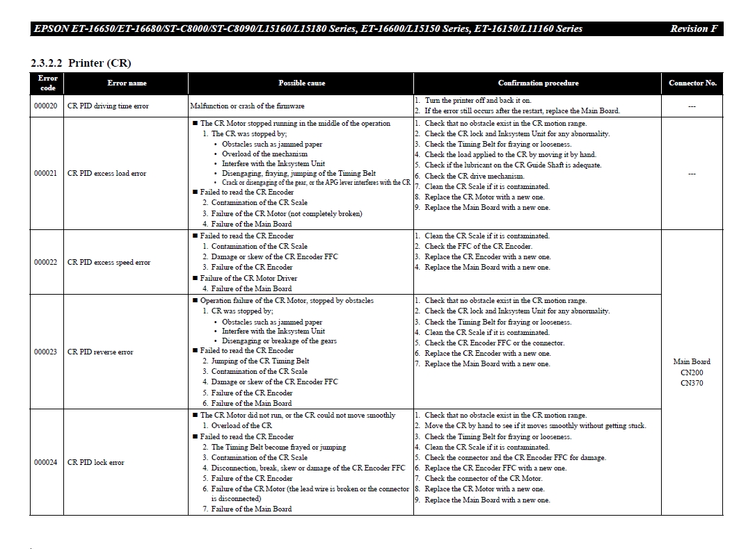
2.3.2.2 Printer (CR).......................................................................................... 67
2.3.2.3 Printer (PF) .......................................................................................... 69
2.3.2.4 Printer (ASF)........................................................................................ 71
2.3.2.5 Printer (2nd ASF)................................................................................. 73
2.3.2.6 Printer (I/S) .......................................................................................... 75
2.3.2.7 Printer (Stacker)................................................................................... 77
2.3.2.8 Printer (RASF)..................................................................................... 79
2.3.2.9 Printer (EJ2 Motor).............................................................................. 81
2.3.2.10 Printer (Head/CSIC) .......................................................................... 83
2.3.2.11 Printer (Others) .................................................................................. 84
2.3.2.12 System Error ...................................................................................... 85
2.4 Normal Error Code List........................................................................................ 86
2.4.1 Printer Error................................................................................................. 86
2.4.2 Network Error............................................................................................ 102
2.5 Status Sheet Information .................................................................................... 107
Chapter 3 Disassembly/Assembly
3.1 Overview ............................................................................................................ 120
3.1.1 Tools .......................................................................................................... 120
3.1.2 Jigs ............................................................................................................. 120
3.1.3 Locations of the Parts/Units....................................................................... 121
3.1.4 Standard Operation Time for Servicing the Product ................................. 123
3.1.5 Checks and Precautions before Disassembling ......................................... 129
3.1.5.1 Factors which Affect the Print Quality ..............................................129
3.1.5.2 Minimizing Ink Leakage during Disassembly for Your Safety.........131
3.1.5.3 Ink Discharging Procedure ................................................................133
3.2 Common Cautions on Disassembly/Reassembly ............................................... 134
3.3 Disassembly/Reassembly Procedures ................................................................ 136
3.3.1 Parts/Components Need to be Removed Before Disassembly/Reassembly.....
136
3.3.2 Functional differences between models and component parts .................. 136
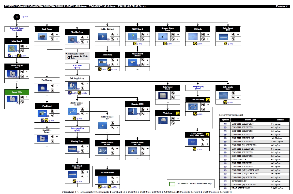
3.3.3 Disassembly Flowchart.............................................................................. 137
3.3.3.1 ET-16650/ET-16680/ST-C8000/ST-C8090/L15160/L15180 Series/ET-
16600/L15150 Series ......................................................................................138
3.3.3.2 ET-16150/L11160 Series ...................................................................144
3.3.4 Repairing Major Components Disassembly/Assembly Procedure............ 150
3.3.4.1 Maintenance Box ...............................................................................150
3.3.4.2 Cover Tank Front...............................................................................150
3.3.4.3 Housing Left ......................................................................................152
3.3.4.4 Housing Right ....................................................................................154
3.3.4.5 Rear ASF Cover Assy........................................................................156
3.3.4.6 ADF/Scanner Unit Assy (ET-16650/ET-16680/ST-C8000/ST-C8090/
L15160/L15180 Series/ET-16600/L15150 Series only).................................158
3.3.4.7 Housing Upper Assy (ET-16150/L11160 Series only)......................159
3.3.4.8 Printhead ............................................................................................161
3.3.4.9 Housing Upper (ET-16650/ET-16680/ST-C8000/ST-C8090/L15160/
L15180 Series/ET-16600/L15150 Series only) ..............................................168
3.3.4.10 Inksystem Unit .................................................................................169
3.3.4.11 Ink Supply Assy...............................................................................172
3.3.4.12 2nd Bin Assy....................................................................................177
3.3.4.13 Main Board ......................................................................................179
3.3.4.14 Rear ASF Unit ................................................................................. 182
3.3.4.15 CR Unit w/CR Guide Shaft ............................................................. 186
3.3.4.16 Paper Guide Upper Left/Paper Guide Upper Center/Paper Guide Upper
Right................................................................................................................ 188
3.3.4.17 Porous Pad A/Porous Pad B............................................................. 191
3.4 Detailed Disassembly/Reassembly Procedure for each Part/Unit...................... 194
3.5 Routing FFCs/cables .......................................................................................... 198
Chapter 4 Adjustment
4.1 Required Adjustments ....................................................................................... 204
4.2 Adjustment Program........................................................................................... 209
4.2.1 Operating Environment ............................................................................. 209
4.2.2 Adjustment and Inspection List................................................................. 209
4.2.3 Details of the Adjustment Program ........................................................... 215
4.2.3.1 Adjustment (Print Adjustment by Mechanical) ................................. 215
4.2.3.2 Adjustment (Print Adjustment by Program)...................................... 220
4.3 Mechanism Adjustment / Check ........................................................................ 227
4.3.1 Checking the Platen Gap ........................................................................... 227
4.3.1.1 PG Adjustment procedure.................................................................. 227
4.3.1.2 Preparation ......................................................................................... 227
4.3.1.3 PG adjustment procedure................................................................... 230
4.3.1.4 Checking the Platen Gap.................................................................... 232
Chapter 5 Maintenance
5.1 Cleaning.............................................................................................................. 234
5.1.1 Cleaning the CR Unit ................................................................................ 234
5.1.2 Cleaning the Exterior Parts/inside of the printer ....................................... 235
5.2 Lubrication ......................................................................................................... 235
5.2.1 Lubrication Points and Instructions........................................................... 236
Chapter 6 Appendix
6.1 Connection Diagram........................................................................................... 242
6.2 Head Fuse ........................................................................................................... 243
6.3 Protection for Transportation ............................................................................. 244
6.3.1 Securing the CR Unit................................................................................. 244
6.3.2 Protection of Stacker Assy ........................................................................ 245
6.3.3 Protection of Cassette Cover ..................................................................... 245
6.3.4 Protection of Scanner Unit (ET-16650/ST-C8000/L15160/L15180 Series/ET-
16600/L15150 Series only).................................................................................. 246
6.3.5 Securing the Tank Cover ........................................................................... 247
6.3.6 Protection of Paper Support....................................................................... 247
6.3.7 Securing the ADF Document Support (ET-16650/ST-C8000/L15160/L15180
Series/ET-16600/L15150 Series only) ................................................................ 248
6.3.8 Securing the Paper Support Cover............................................................. 249
6.3.9 Securing the Maintenance Box.................................................................. 249
6.3.10 Securing the Rear ASF Cover Assy (ET-16150/L11160 Series only) .... 250
Related Products
Check items to add to the cart or


Validate your login