This website uses cookies to ensure you get the best experience on our website. Read more
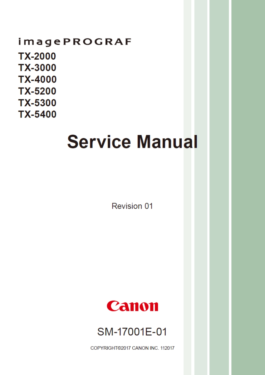
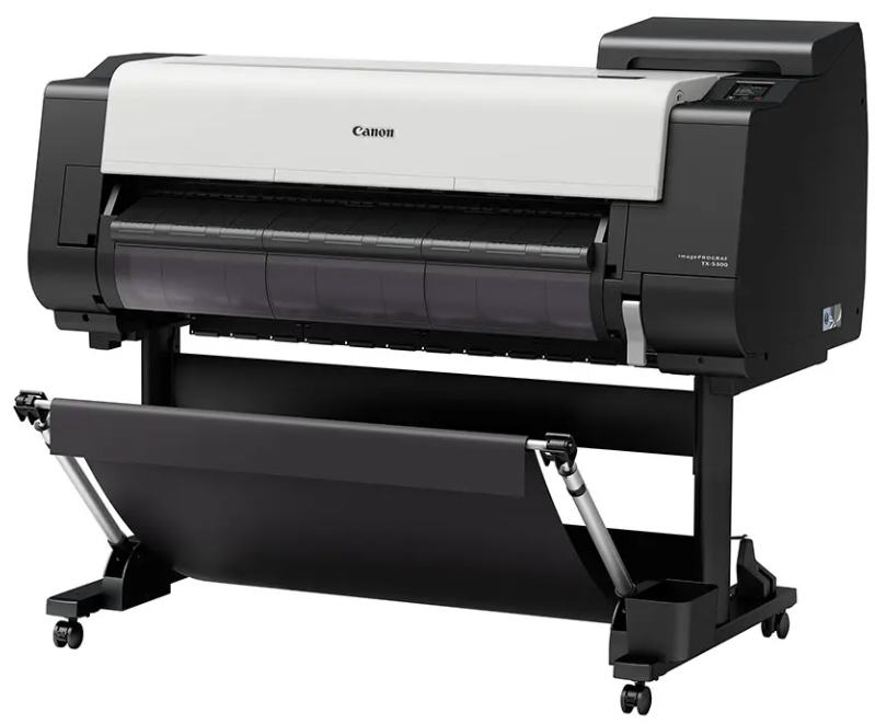
Canon imagePROGRAF TX-2000 TX-3000 TX-4000 TX-5200 TX-5300 TX-5400 Service Manual
In stock
SKU
CN-TX3000-SM
$9.90
- Email with download link immediately
- Files without viruses
- PDF format manual
- Allow high-definition printing
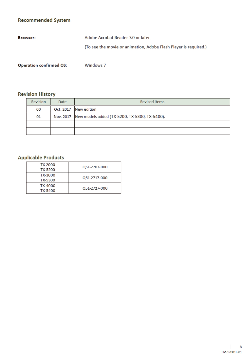
| Manual Name | Canon imagePROGRAF TX-2000 TX-3000 TX-4000 TX-5200 TX-5300 TX-5400 Service Manual |
|---|---|
| Format | |
| PDF Archive | 74.7M |
| Pages | 826 |
| Version | 01 (second edition) |
| Brand | EPSON |
| Parts Code | SM-17001E-01 |
| Reference | 2017.11 |
| Type | SERVICE or PARTS MANUAL |
| Compatible Model | . |
Canon imagePROGRAF
TX-2000 TX-3000 TX-4000 TX-5200 TX-5300 TX-5400
Service Manual

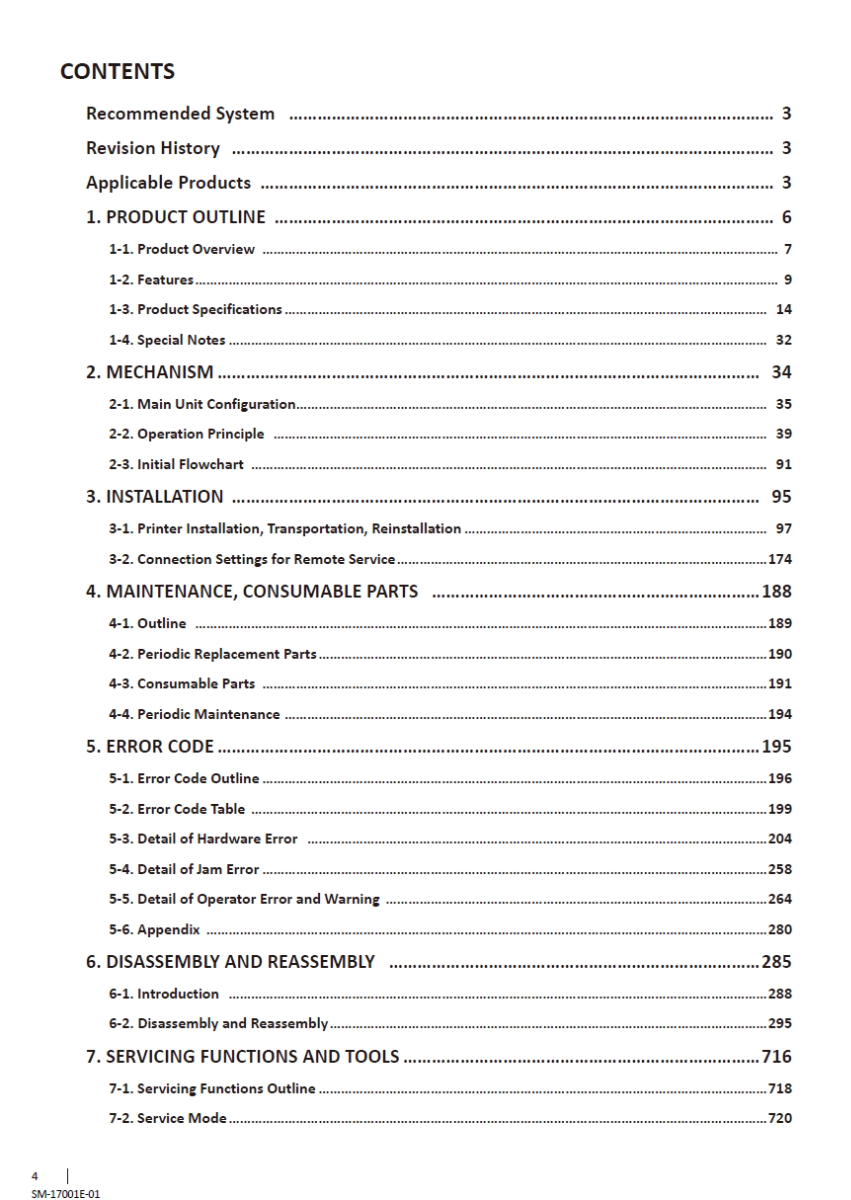

CONTENTS
Recommended System… ………………………………………………………………………………………… 3
Revision History… …………………………………………………………………………………………………… 3
Applicable Products… ……………………………………………………………………………………………… 3
1. PRODUCT OUTLINE … …………………………………………………………………………………………… 6
1-1. Product Overview… ………………………………………………………………………………………………………………………… 7
1-2. Features…………………………………………………………………………………………………………………………………………… 9
1-3. Product Specifications…………………………………………………………………………………………………………………… 14
1-4. Special Notes………………………………………………………………………………………………………………………………… 32
2. MECHANISM ……………………………………………………………………………………………………… 34
2-1. Main Unit Configuration……………………………………………………………………………………………………………… 35
2-2. Operation Principle… …………………………………………………………………………………………………………………… 39
2-3. Initial Flowchart… ………………………………………………………………………………………………………………………… 91
3. INSTALLATION …………………………………………………………………………………………………… 95
3-1. Printer Installation, Transportation, Reinstallation………………………………………………………………………… 97
3-2. Connection Settings for Remote Service…………………………………………………………………………………………174
4. MAINTENANCE, CONSUMABLE PARTS … ……………………………………………………………188
4-1. Outline… ………………………………………………………………………………………………………………………………………189
4-2. Periodic Replacement Parts……………………………………………………………………………………………………………190
4-3. Consumable Parts… ………………………………………………………………………………………………………………………191
4-4. Periodic Maintenance……………………………………………………………………………………………………………………194
5. ERROR CODE ………………………………………………………………………………………………………195
5-1. Error Code Outline…………………………………………………………………………………………………………………………196
5-2. Error Code Table……………………………………………………………………………………………………………………………199
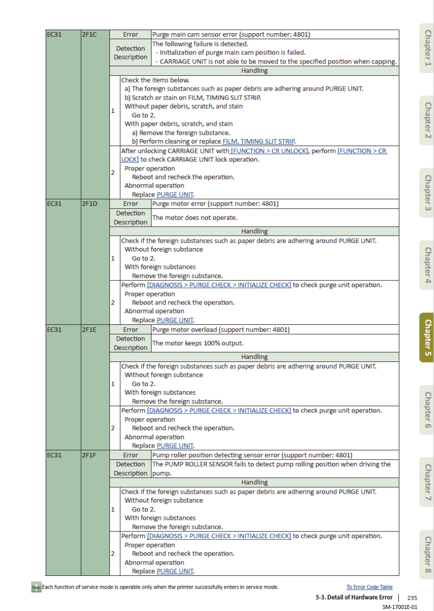
5-3. Detail of Hardware Error… ……………………………………………………………………………………………………………204
5-4. Detail of Jam Error…………………………………………………………………………………………………………………………258
5-5. Detail of Operator Error and Warning……………………………………………………………………………………………264
5-6. Appendix………………………………………………………………………………………………………………………………………280
6. DISASSEMBLY AND REASSEMBLY … ……………………………………………………………………285
6-1. Introduction… ………………………………………………………………………………………………………………………………288
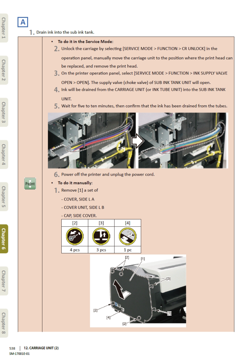
6-2. Disassembly and Reassembly…………………………………………………………………………………………………………295
7. SERVICING FUNCTIONS AND TOOLS ……………………………………………………………………716
7-1. Servicing Functions Outline……………………………………………………………………………………………………………718
7-2. Service Mode…………………………………………………………………………………………………………………………………720
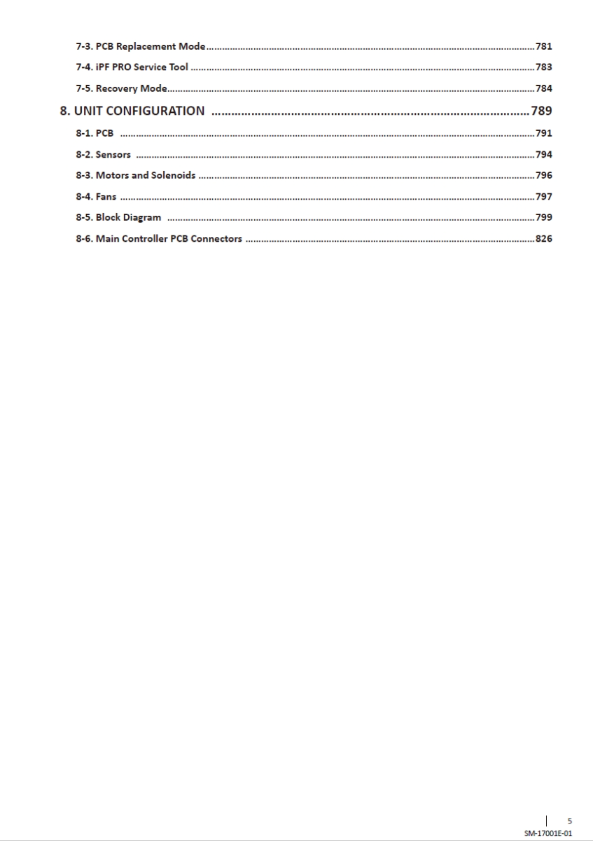
7-3. PCB Replacement Mode…………………………………………………………………………………………………………………781
7-4. iPF PRO Service Tool………………………………………………………………………………………………………………………783
7-5. Recovery Mode……………………………………………………………………………………………………………………………784
8. UNIT CONFIGURATION … ……………………………………………………………………………………789
8-1. PCB ………………………………………………………………………………………………………………………………………………791
8-2. Sensors… ………………………………………………………………………………………………………………………………………794
8-3. Motors and Solenoids……………………………………………………………………………………………………………………796
8-4. Fans………………………………………………………………………………………………………………………………………………797
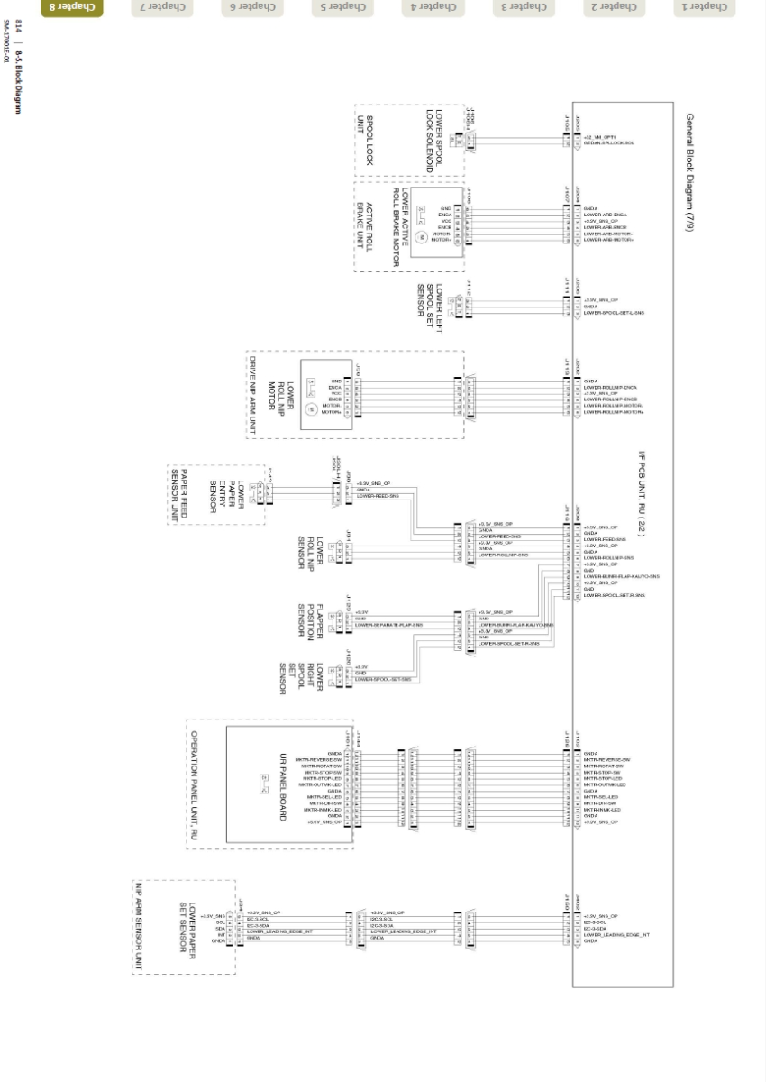
8-5. Block Diagram… ……………………………………………………………………………………………………………………………799
8-6. Main Controller PCB Connectors……………………………………………………………………………………………………826








Validate your login