This website uses cookies to ensure you get the best experience on our website. Read more
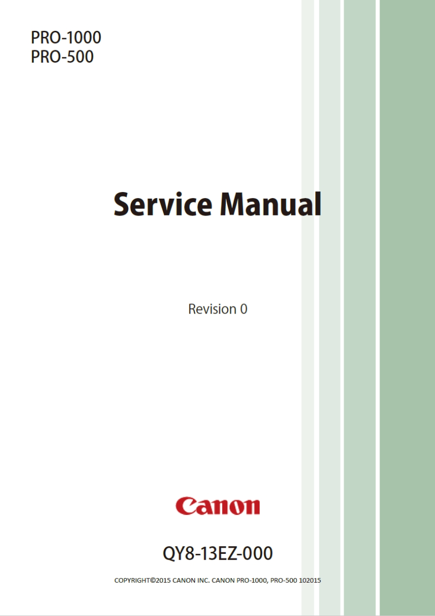
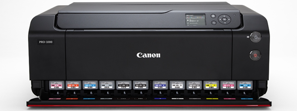
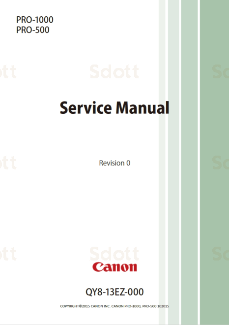
Canon imagePROGRAF PRO-1000 PRO-500 Service and Parts Manual
In stock
SKU
CA-PRO1000-SM
$9.95
- Email with download link immediately
- Files without viruses
- PDF format manual
- Allow high-definition printing
| Manual Name | Canon imagePROGRAF PRO-1000 PRO-500 Service and Parts Manual |
|---|---|
| Format | |
| PDF Archive | 276M |
| Pages | 471 |
| Version | 0 |
| Brand | CANON |
| Parts Code | QY8-13EZ-000 |
| Reference | 2015.10 |
| Type | SERVICE or PARTS MANUAL |
| Compatible Model | CANON imagePROGRAF PRO-500 CANON imagePROGRAF PRO-1000 |
Canon imagePROGRAF PRO-1000 PRO-500
Service and Parts Manual


CONTENTS
Manual Configuration................................................................................................ 3
Recommended System Requirements........................................................................ 4
TROUBLESHOOTING.................................................................................................. 7
Check Points.............................................................................................................................................. 13
By Symptom.............................................................................................................................................. 14
By Printout Condition................................................................................................................................ 29
Troubleshooting for Color Matching.......................................................................................................... 40
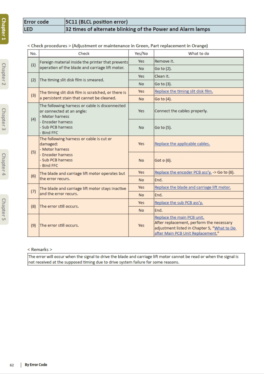
By Error Code............................................................................................................................................ 49
Error List..................................................................................................................................................144
COLOR CALIBRATION............................................................................................. 151
Color Calibration......................................................................................................................................152
DISASSEMBLY & REASSEMBLY................................................................................ 161
Disassembly Procedures...........................................................................................................................167
Print Head External Housing 167
Purge Unit 184
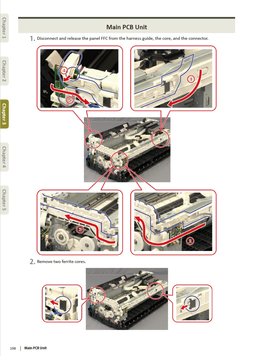
Main PCB Unit 196
Carriage Unit 207
Auto Sheet Feeder Unit, Blade and Carriage Lift Motor 216
Spur Unit, Platen Unit, Paper Feed Roller 230
Ink Supply Unit 257
Assembly Procedures...............................................................................................................................273
Ink Supply Unit 273
Spur Unit, Platen Unit, Paper Feed Roller 290
Blade and Carriage Lift Motor, Auto Sheet Feeder Unit 321
Carriage Unit 340
Main PCB Unit 351
Purge Unit 366
Print Head External Housing 376
Print Head Replacement Procedure..........................................................................................................393
In User Mode 393
In Service Mode 397
ADJUSTMENT & VERIFICATION AFTER REPAIR........................................................ 401
Adjustment..............................................................................................................................................403
Cleaning...................................................................................................................................................458
Verification after Repair...........................................................................................................................459
PARTS CATALOG..................................................................................................... 463
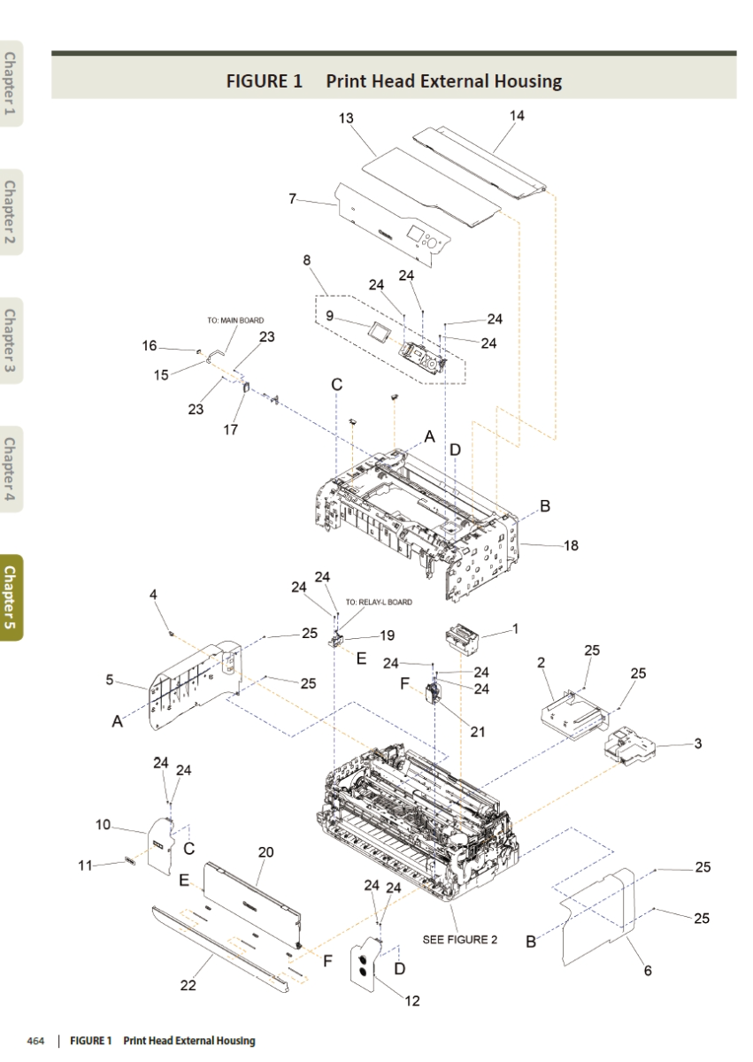
FIGURE 1 Print Head External Housing..................................................................................................464
FIGURE 2 Purge Unit.............................................................................................................................465
FIGURE 3 Main PCB Unit.......................................................................................................................466
FIGURE 4 Carriage Unit.........................................................................................................................467
FIGURE 5 Auto Sheet Feeder Unit, Blade and Carriage Lift Motor..........................................................468
FIGURE 6 Spur Unit, Platen Unit, Paper Feed Roller...............................................................................469
FIGURE 7 Ink Supply Unit......................................................................................................................470
FIGURE 8 Option and Consumables.......................................................................................................471





Validate your login